Levi asked me to make Dungeons & Dragons dice for him. Some research on the web indicates six dice are needed. One of each of the Platonic solids: 4, 6, 8, 12, and 20, plus two 10-sided dice are standard. The original request was for wood, but wood does not make very accurate dice, with most of them giving biased rolls. Metal dice last forever, but need to be rolled on a mat to avoid damaging a wooden table or board. The standard size is 16 mm or 5/8".

So far I have come up with one approach that might work. The six-sided die is easiest as it is a cube. The rest present challenges in determining angle, setting depth of cut, and holding the work piece while machining. My thought is that one or two faces will be drilled for a spud. The spud can be held in the rotary table and the whole part cut and rotated as needed. A test run was in order.
The 8-sided die was to be explored first. If it is held with one face flat against the table, three faces can be milled 120° apart. Holding on the opposite face allows three more faces to be milled. I had a piece of 3/4" brass rod handy, that was ~5/8" long. This brass was faced on both ends, drilled and reamed 3/16" through.
A piece of 3/16" brass rod was cut off at 1 1/8". Both ends were faced. The stock was slightly under 3/16" so the rod was too loose in the hole to even glue in place. The rod was knurled in the center and could then be forced into the hole and remain tight. The cylinder with rod is shown next to the target die.

The cylinder with a 1/4" of rod emerging from each end was held in the chuck mounted on the rotary table. The angle of the headstock was set to 71°. A face was milled to a depth, from just touching the corner, of 0.160". The double insert end mill came to depth at 0.100" where the cut edge met the cylinder plane. An extra 1/16" was then cut off leaving a lip. The cuts were made in passes from 0.010" initially to 0.005" for the last dozen passes. The table was turned 120° and the cut was repeated. After three cuts the part was flipped end for end in the chuck using the opposite end of the rod to hold the part. The part was oriented so one cut face was parallel with and opposite to the next face to be cut (or parallel to the y-axis). Photos of the setup and different stages of milling are shown below.


This part was not expected to become a die. The diameter of the octahedron is 7/8", so the starting cylinder was not large enough. In addition the milling setup was not quite right for milling a full die. The spindle was set at its lowest extreme, but this was not low enough to hit the center of the cylinder. A belt was left around the middle. On the other hand the dihedral angle between milled faces was spot on. The orientation of the part after the flip also was sufficiently accurate . In other words this turned out to be a successful trial run. The scrap is shown next to its plastic counterpart in the photo below.

Now for the real thing. First, the 8-sided die was measured. The point to point distance is 0.950". The edge to opposite edge is 0.718" and the face to opposite face is 0.617". The edges and vertices are rounded, so these measurements should be a bit (1/16") higher. The biggest challenge in cutting the faces is knowing how deep to cut. A little math with the above dimensions implies the cutting depth should be 0.258". A double check will be a scribed line at the center of the cylinder. Each face should be cut to this line. The cylinder will start as a 1" brass round that is 1 1/8" long.
A 1 1/8" length of 1" brass round bar was cut off with a hacksaw. It was faced in the lathe on both ends. One end was reduced to 0.250" diameter for 0.250". The stub and the edge of the part were deburred. The stub was held in a collet and the opposite face was similarly reduced to a stub. The OD of the central portion was reduced to 0.950". Dykem was applied and a line scratched at the center of this part. This part can be seen set up in the chuck on the rotary table ready for milling. Note the rotary table is set on the closed angle plate for additional height.

The end mill was lowered (not enough) and the edge was located with the cutting edge of the end mill. The end mill was advanced in 0.010" increments for the first 0.050" and then advanced in 0.0075" increments for the next 0.045". At this point the x-axis was advanced in increments of 0.005". The end mill was not sufficiently lowered, so the x-axis was backed off, the spindle lowered so its lowest extent was below the part. Milling resumed and continued until the edge length was 0.715". At this point it was clear that the scribed central line was useless as the cut extended below the part.
It was not clear how to determine the depth of cut. The calculation assumed the part was moving along the axis of the spindle, which is impossible. So I winged it. The rotary table was turned 120° and the milling was repeated until the same side length was reached. This left 9/64" between the two edge ends seen in the photo below. Cutting on this edge continued until a bit more than 4/64" was left between ends. The table was rotated around to 0° and the first side was cut further. When the two edges met at a point, both sides were 53/64" long. At that point the part had moved a total of 0.220" along the x-axis.


The table was rotated to 240° and the cut was repeated a third time. At a cut depth of 0.220" the last edge met the other two at points. The part at this stage of milling is shown below. It takes about 1/2 hour of milling per side.

The fledgling octahedron was loosened in the chuck and flipped over so the opposite spud was now held in the chuck. It was rotated so one of the cut faces was parallel to the y-axis of the table. An adjustable parallel and a ruler were used against a clamped block of aluminum to assure the face was oriented as square as possible. The photo below shows the setup.

The remaining three faces were cut as above. All three faces had to be cut deeper, 0.030", than the previous three in order to come to a point. Once the part was removed an issue was quickly recognized. The bottom vertices formed from the last three cuts were not points, but flats. After some measuring it was discovered that the distance between the two faces with spuds is 0.050" less than the desired 5/8"! One other issue was discovered during the milling. The chuck jaws were nicked on the last few cuts. When repeated these jaws need to be offset better. The photos below show the completed milling and the flat on one of the vertices.


The completed and flawed octahedron from above presents a final challenge, how to remove the stubs. One could be milled, but the second will need to be cut off and filed/sanded flush.
The spuds were removed. A washer was placed over the spud and it was sawed off leaving 1/16". The stub could be filed pretty close, about 1/32". Further filing or sanding on the wheel was difficult without hitting the edges. The remainder was removed by sanding with 150 grit. All sides were then sanded with 220, 320, 400, and 600 grit sandpaper. The first photo shows the finished, but marred octahedron. The second compares it to the model.


Decided to make yet another octahedron. This time the disk between the studs was sized to 0.625". The angle of the spindle had not been changed, so was used again. The first cut went to 0.220" in on the x-axis. The second cut cleared the bottom at about 0.205" and met the first edge at 0.195". Milling was continued to 0.220" so the sides would remain symmetrical. When making the third cut the ends were not symmetrical with respect to the ends of the first two cuts! The part has slipped in the chuck! The angle between the first two cuts was closer to 70° than 60°.
Back to the lathe once again. The part was made as above and this time care was taken to check the chuck tightness after each cut. The cuts were made to 0.210" as that is the theoretical prediction. This leaves about 1/16" between the ends of two cuts. These flats are fine as the vertices will eventually be rounded. The picture below shows the part after the first three faces were cut.

The part was flipped over, aligned as above, and the chuck tightened. The last three faces were cut, again to 0.210" depth. The edges on the top/bottom are the same length as the edges along the sides, 0.750", where top and bottom refer to the faces with stubs. The photo below shows the completely milled octahedron.

The spuds were cut off as before and then sanded flush with 120 grit sandpaper. All sides were then sanded up to 600 grit. All edges and vertices need to be rounded over, but I am not sure how to do this to achieve a consistent look.
The tetrahedron is next to be made. The dihedral angle is 70.5°, so I will use the same setup on the mill and not change the 71° angle of the spindle. The side length is almost 13/16", 0.8125", and approximately defines the diameter of the cylinder from which it will be made. The height of the tetrahedron is 0.680 with its rounded corner, so a 0.700" high disk should suffice. Depth of cut will be to the center of the cylinder.
The scrapped part from the octahedron that slipped in the vise had one spud cut off with the hacksaw. The other spud was held in the collet and the cut off end was faced. The resulting "disk" was slightly below what was planned at 0.665". The diameter was reduced to 0.812" and the part was transferred to the chuck on the rotary table. The three sides were milled in 0.0075" increments to within 1/64" of the center point, leaving a small triangle. This same tiny triangle was also left at the other three corners formed when adjacent faces were completed. The first picture below shows the recycled part after the first cut. The second is after two faces of the tetrahedron are complete and shows the small flat on the lower back corner. The third shot is the almost completed tetrahedron after deburring, but with the spud still attached.


After cutting off most of the spud, the remainder was sanded off first with the disk sander and then by hand with 150 grit sandpaper. The four faces of the tetrahedron were sanded to 600 grit. The tetrahedron and the octahedron are seen in the photo below.

The dodecahedron with twelve pentagonal faces should follow the same pattern as the octahedron. Two opposite faces serve as spud locations allowing the milling of five faces, while each spud is held in the chuck. The dihedral angle of the dodecahedron is 116.57°, which indicates the spindle should be set at 180 - 116.57 = 63.43°. The dodecahedral die Levi loaned me has opposite faces separated by 0.700". Using the two formulas for circumscribed and inscribed spheres. The diameter of the inscribed sphere is the distance between opposite faces, so the length of an edge of this dodecahedron is 0.350 / 1.114 = 0.314". The vertex to opposite vertex diameter is 0.314 X 1.401 X 2 = 0.880". Consequently, the "disk" for milling should be 0.88" in diameter and 0.70" thick. The little radius of the pentagon, distance from center of a pentagonal face to its edge is given by 0.314 X 0.6882 = 0.216", the depth of cut is then 0.440 - 0.216 = 0.224". The same trick used above can be used to align the part after flipping to the opposite spud as all opposite faces are parallel.
So let's get started on the second dodecahedron I have made, see first. This dodecahedron will be a lot easier. A 1 1/4" length of 1" brass round was cut off with a hacksaw. The part was chucked in a four jaw chuck and faced on both ends. One end was reduced to 0.250" for 0.250". This reduced end was held in a collet and the opposite end reduced similarly. The large cylinder was reduced in length to 0.70" and in diameter to 0.88". The photo below shows the dodecahedron blank ready for milling the remaining ten faces.

When adjusting the headstock angle the motor came loose! Taking it apart, adjusting the motor mount offsets, reassembling, and waiting for the Loctite to harden, caused a slight delay. Eventually the motor was reattached and the spindle set to 63.4° using a new level app, Pocket Bubble Level XXL. After setting the spindle height the first five faces were cut, rotating 72° between each cut. The photo below shows the part halfway through the milling. Notice the milling into the spud.

The part was removed from the chuck and flipped end for end in the three jaw chuck. A cut face was aligned square to the table. Milling then proceeded on the remaining five faces. This went well as seen in the photo below. The sides on the top pentagon were measured and compared to the middle pentagons. All are within 1/64" of 19/64" indicating the angle and depth of cut were sufficiently accurate.

The spuds were cut off and the remainder was sanded off with the disk sander and by hand on 120 grit sandpaper. Sanding all twelve sides up to 600 grit completed the dodecahedron.

Time to whip out a cube. The cubic die in Levi's set is 0.620" width. A short length of 3/4" square brass stock was located and an 11/16" piece was cut off with a hacksaw. This was held in the four jaw chuck on the lathe and faced on both sides reducing the distance between faces to 0.62". One of the two parallel faces was set on a ball bearing in the vise on the mill and set to the vertical. The top face was milled. The part was flipped over and set firmly on parallels. The exposed face was milled to dimension. This process was repeated for the remaining two faces and produced the cube seen below after deburring. The cube was checked with a square and was square as judged by light showing between the cube and the square's blade on all edges.

An icosahedron has twenty triangular faces. Similar to the cube, octahedron and dodecagon it has a mirror plane between all opposing faces and can be set up and milled the same way with two opposing spuds. Levi's die is 0.770" from one face to its opposite. It is 0.900" from one rounded vertex to it opposite. The dihedral angle is 138.19°. The radius of the inscribed sphere or the face to face distance is equal to 0.755761 times the edge length. So the edge length of the planned icosahedron is 0.770 / 2 / 0.755761 = 0.509. Similarly, the calculated vertex to vertex distance is 0.509 * 0.951057 = 0.952", almost a 1/16" more than when measuring the rounded corners. So our cylinder for this die is 0.952" diameter and 0.770" tall.
I am going to need to purchase more 1" brass round bar stock. A 1 3/8" length of brass was cut from the remaining bar. The part was turned into the usual cylinder with two spuds as seen in the photo below, where it is already clamped in the chuck for milling. Three triangles surround the spud's face at their dihedral angle of 138.2°. These three triangles have six triangles below them defining their edges and completing the top ten sides of the icosahedron. How to cut these six is not yet clear, but the top three can be cut with the spindle set at 180 - 138.2 = 41.8°.

The spindle was set to 41.8° adjusted for the -0.3° tilt of the column. The two insert end mill was set to just touch the top edge of the cylinder. The depth of cut for these first three triangles is the cylinder diameter minus half the height of a triangle. Triangle height is the square root of 3/4 of the side squared or 0.441". So the DOC is 0.952 / 2 - 0.220 = 0.256". The three cuts were made, rotating the table 120° between each. The photo below shows the result.

The sides of the new triangle were measured at 3/4"! A rough measurement of the plastic icosahedron indicates the depth of cut should be closer to 3/8". The point of the triangle is 0.256" from the circumference of the starting cylinder! A bit more geometry indicates that the desired depth of cut is 0.256 plus the distance from the triangle bottom to the circle circumscribing the triangle or 0.349". The three faces were cut to 0.300" and the side length was a bit over 1/16" long, so an additional 0.020" was removed from each face, bring the side length down to 0.51" as close as I can measure. So a total depth of cut of 0.320" will be used on the opposite end of the cylinder. As seen below the opposite face is now complete.

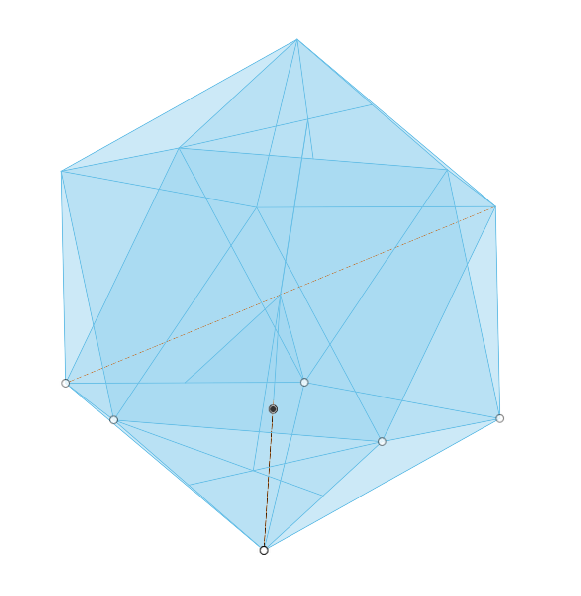
A very unproductive two days was spent attempting to first find someone on line sharing the correct angles. None were found, except one woodworker setting his bandsaw at 21° and keeping a face on the table. I then went into the land of Fusion. I found a video of the production of an icosahedron using the loft command followed by circular repetitions of the resulting construction. At one point a pentagon is surmounted by a point that is the top vertex of the icosahedron. A similar point was constructed under the plane of the pentagon giving the midpoint of the icosahedron. The next step is to use a loft to connect all the points with solid sides. I couldn't get his actions to produce the same design on my screen trying many different things. The best I could get were curved sides!
After many hours and much frustration, I found a second icosahedron construction. This construction used only equals constraints to always produce equilateral triangles and to set the dihedral angles. There were a few things that did not work in my hands. For example, at one point a pentagonal pyramid has been produced. Five triangles are suspended from the bottom of this pyramid, though their dihedral angles have not been set. The bottom of two triangles are joined and a circular pattern is used to join the other four gaps. This did not work for me, leaving unjoined edges. Instead I just drew in each line, making sure the equals constraint was used each time as needed. Eventually I produced the desired icosahedron, seen below.
The next challenge was drawing the necessary lines to measure the angles needed for milling the remaining faces. The midpoint of a face was located with two lines running from corners to midpoints of opposite sides. A line from this point was dropped to the center line between opposite faces. The line was made perpendicular to the face. The angle of this line with the vertical center line was measured at 70.5°, confirming the advice of the woodworker.
With the angle of the headstock in hand the angles between faces were determined, though not as originally planned. It was easy to determine the angle between one of the three faces already cut and an adjacent triangle, just measuring from the midpoint of the new triangle to the bottom vertex of the cut triangle, -31.7°. Trying to measure the angle between this triangle and the triangle joined by a line was confusing, so I went simpler direction. Proceeding from the triangle just cut across the bottom vertex of the reference triangle leads to movement by twice the previous angular movement, 63.4°. So to make the cuts for the two faces on opposite sides of one of the three first cuts, align the reference cut, go -31.7° or 328.3°, cut the new face, advance 63.4°, cut the second face. Now move to each of the remaining first three cuts and repeat.
There are three of the above described 63.4° angles. Removing these from 360° divided by three gives 56.6° as the missing angle, if I decide to go that route.
The ideas and angles generated above were implemented. The table was rotated to 328.3° and the cut was made to a depth of 0.135", which just hit the point of the first triangle with the spud. After rotating the table 63.4° (31.7° setting on the rotary table), the second cut was taken also to a depth of 0.135". These first and second cuts are shown below. Rotation to first 88.3° (120 - 31.7) and then to 151.7° (+ 63.4) and cutting to the same depth gave the second two cuts. Further rotation to 218.3° and 281.7° set up the last two cuts. The 218.3° cut did not go to depth before reaching the point. This last triangle looks a bit skewed! Two views of the part at this stage are shown below. The skewed triangle is in the upper left in the last photo. Did the part slip in the chuck or are my angles wrong?


Unable to fix this mistake I pushed on wanting to see how close I could get to an icosahedron. The part was flipped over after setting the table back to 0°. It was aligned as before so a cut face was pointing toward the spindle. The same set of cuts as above were made. This produced something vaguely reminiscent of an icosahedron as seen in the photo below. The cuts on this side also yielded a skewed triangle implying my angles are incorrect. The other wonkiness around the middle is somewhat consistent and is probably a result of not orienting the part correctly with respect to the opposite side after flipping it over.
The point of the skewed triangle is off by almost 1/8", the first and second are off less, but the error is noticeable, when measuring the sides, all less than 0.5". One or more angles must be incorrect! I don't understand why the third triangle is so much more skewed than the other two. The errors should not be cumulative, the way they were calculated. The angle from the top spud face to one of the newly cut faces is 108°, very close to the expected 109°, though my measuring could account for the difference. The pseudo-icosahedron will be used for exploring methods for numbering the sides, before adding it to the scrap heap.

Logic tells me that the angle over the flats is the dihedral angle, 138.2°. So rotating 180 - 138.2 = 41.8° should be the correct table rotation between cuts over the edges. This implies the rotation between the cuts I made should have been 78.2°, not 63.4°. The offset from the previously cut sides should have been 39.1° instead of 31.7°. More brass was ordered as I have used up my 1" round bar stock.
I initiated a discussion in the Home Shop Machinist forum. Two suggestions were useful. The first was to use a low melting alloy to hold the ten sided die in a cone. Some was ordered from RotoMetals. The second suggestion was to use the plastic icosahedral die to determine the rotation angles. The die was held on parallels in the milling vise mounted on the rotary table. Not a very stable arrangement as only two edges are really held, but enough for this process. The table was turned until one of the three first cut faces was aligned as determined by traverse with a dial gauge.
The faces are not very flat and the part was not perfectly centered over the table, making for a challenging process. A ruler was held to the measured flat to provide a flatter measuring surface, but even holding it flat to the small faces was difficult. In any event the following three rotary table angles were determined: 215.2°, 253.1°, and 296.0°. This gives the two angles needed: 37.9° and 42.9°. The latter is pretty close to the expected 41.8° rotation between the two flats connected by an edge. the former, 37.9°, is not too far off of the 39.1° predicted above. The photos below show the aligning process with and without the rule, though in practice the rule had to be held in place by hand when moving the table on the y-axis.


The measuring was attempted again before proceeding, though the boys are spending the weekend here, so there won't be any progress for a few days. The rotary table was centered under the spindle. A pointed piece of steel was made to fit the spindle collet. The vise holding the plastic icosahedron was centered under this point using the side with the "1". After quite a bit of fiddling this was accomplished.
The boys are gone and new brass has arrived. the angular measurements were taken this morning. the measured rotation from one of the three flats surrounding the top flat is 38.5°. The angle over an edge to the next face is 43.6° and the angle from this face, over a point to the next is 76.9°. As before holding the rule over a face is challenging and I also realized the ruler needs to be held close to level to avoid yet another source of error. the 43.6° rotation should have been 41.8° as this is a dihedral angle. This highlights the error associated with this method, ±2°. These measurements are all in accord with the predictions made four paragraphs previously. I will now try 39.1° from the first three flats to the first second level flat and then 41.8° to the next flat across an edge.
The cylinder with two spuds was made as above, 0.770" tall and 0.952" in diameter. Three sides were cut, 120° between each, to a depth of 0.320". The sides of the triangles thus formed are 0.51" long. The photo below shows the die at this stage after both ends have been cut.

With the die still in place and the table at 240°, the table was rotated 39.1° to 279.1°. The headstock was set at 71° with the Measure app on the phone as the app downloaded seemed very imprecise! The face was cut and reached the vertex of the top triangle at a depth of 0.140". The table was rotated to 320.9° and the second face was cut to the same depth. This process was repeated at 39.1° followed by 80.9° and the last two cuts at 159.1° and 200.9°. The first photo below shows the part after cutting these six faces. The part was flipped over and one of the first three faces cut was aligned as done before. The same sequence of six cuts was made to the same depth producing my first icosahedron as seen in the second photo below. It is not quite perfect as tiny lines can be seen connecting triangles around the middle. I think it is good enough and sanding should clean up the lines.


The icosahedron had the spuds removed with a hacksaw, while protecting the faces with a washer. The remnants of the spuds were sanded off with the disk sander. All twenty faces were sanded 120 through 600 grit. The resulting icosahedron and the other four Platonic solids are pictured below.

The D10 dice are called pentagonal trapezohedrons! They are the only dice used in D&D that are not Platonic solids. Two are used to roll numbers from 0 - 99. The dihedral angle between the top and bottom faces is 90°. The dihedral angle between the adjacent five faces on each half is 130°. Using two spuds on opposite faces will not work with these dice as there is no mirror plane between faces. Using one stud on a face will allow milling four of the other nine faces with the spindle set horizontal. Milling the other five sides with this setup requires a spud in a different face not opposite to the first. As shown in the table below there are no two numbered faces that provide access to all of the other eight faces, so the two spud route is out.
| Bot. Face | Available Sides for Milling | |||
|---|---|---|---|---|
| 0 | 2 | 3 | 6 | 7 |
| 1 | 3 | 4 | 5 | 6 |
| 2 | 0 | 4 | 5 | 9 |
| 3 | 0 | 1 | 8 | 9 |
| 4 | 1 | 2 | 7 | 8 |
| 5 | 1 | 2 | 7 | 8 |
| 6 | 0 | 1 | 8 | 9 |
| 7 | 0 | 4 | 5 | 9 |
| 8 | 3 | 4 | 5 | 6 |
| 9 | 2 | 3 | 6 | 7 |
A possibility is using spuds emerging from the top and bottom vertices, where five triangles meet. Milling would progress to the spud. Sanding would finish the faces after sawing off most of the spud. This would take a lot of sanding and would require adjusting the cutter so it hits the bottom of the spud as correct depth of cut is reached. That is, the apical vertex would be buried in the spud and see the light of day only after sanding.
As mentioned above some low melting metal was purchased from Roto Metals. It is a bismuth based allow melting at about 160° F. The plan is to again start with an appropriately sized cylinder of brass. Hold this in the three jaw chuck on the rotary table. Set the spindle to 45° and cut five faces to a common vertex. An inverted cone will then be made to hold the cut side of this part using the metal as glue, a common use for this metal. The challenge will be ensuring the part is centered and concentric with the inverted cone jig. Using the same diameter for the jig as for the part may help with alignment.
Not knowing how to calculate the various sizes of this PT, approximations will be made based on the sample pair of dice. The starting cylinder will have a diameter of 0.900" and a height of 0.825, both measurements about 1/16" above measuring from rounded corner to rounded corner. The cylinder was made to the dimensions above. It was mounted in the three jaw chuck on a 1/4" scrap of aluminum (1/8" would have been sufficient). The table was set to 0° and the spindle set to 45°. The corner was located with the end mill and cutting proceeded in 0.010" increments of the x-axis. The center of the cylinder was reached at 0.445". The table was rotated 75° and the milling was repeated. Three more times and one half of the PT was complete as shown in the photo below.

As a slight diversion before tackling the second PT an inverted cone was made for holding the part while milling the opposite side. A scrap of 1" brass round was held in the three jaw chuck and faced on both ends. One end was then drilled with a center drill and an E drill (sharper than the 1/4" drill) 1/4" deep. The head of the lathe was rotated 45°. A small boring bar was mounted and height adjusted in the holder on the QCTP. The boring bar was mounted upside down so as to cut on the back side of the hole. The 90° internal cone was cut in 0.01" passes easily with the boring bar. The cross slide was somewhat overextended and pressure was applied to the tool holder top during the cuts to avoid tool lifting and chatter. The first photo shows cutting in progress. The diameter of the fixture was reduced to 0.900" for 1/2" matching the diameter of the PT. The completed fixture is seen with and without the inserted, half cut PT below. The second pentagonal trapezohedron was also machined to the halfway point as seen in the fourth photo below.


Yes, the second PT is taller than the first, not an optical illusion. Someone forgot to face the cylinder to size! It was faced to size after a quick measurement showed it was 1/16" too tall.
Aligning the half cut PT in the fixture is vital to successfully cutting five facets on the other side. To this end a simple addition to the fixture was quickly made this morning. A scrap of aluminum about 1 1/4" in diameter was faced on one end and drilled through up to 1/2". It was bored to 0.90" until the fixture and both PTs were an easy fit. The opposite end was faced. The ring and the fixture are shown in the first photo below along with the second photo of the ring in place aligning a half finished PT.


An old aluminum pie pan was grabbed from the kitchen, meanwhile water was heating in the water kettle. When the water was 200° it was poured into the pan. One half cut PT was put in the pan along with the fixture loaded with the bismuth alloy and the aluminum ring. The metal did not melt. The water was replaced and then replaced again with hot water, still no melting. I pulled out the torch and quickly melted the bismuth alloy. The PT was placed in point first, but did not stick. The metal solidified too quickly. The photo below shows the pan with parts.

The PT and fixture with the alloy were placed on the vise and both heated with the torch. The metal quickly melted. After a minute of heating the PT was placed in the fixture squeezing out some alloy. The outside of the fixture was wiped with a shop towel and the ring was put in place. The entire setup was left to cool in the 40° garage. The photo below shows the setup after hot assembly.

After cooling to garage temperature the ring was removed. The PT came right out of the fixture. There was absolutely no attachment to the cooled bismuth alloy as seen below. The alloy did stick to the fixture! The part is probably too smooth for the alloy to stick, though it is just the mill finish, which feels slightly rough when scraped with a fingernail. I will switch to epoxy, with hopefully more success.

A small amount of T-88 epoxy was mixed up and put into the fixture. The PT was put in place. The outside was wiped off and the ring put in place. The photo below shows a bit of epoxy peeking out between fixture and PT before putting the ring in place. The package states full cure in 72 hours!

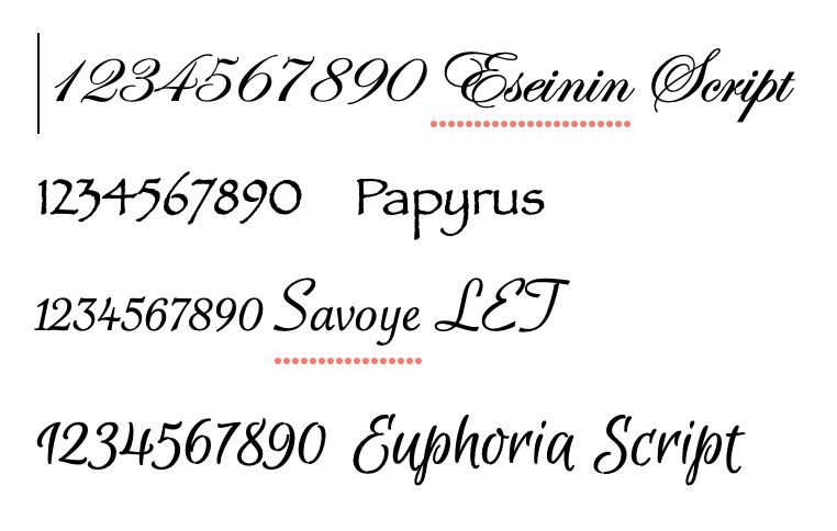
In the meantime I should practice engraving small numbers. Four potential fonts were selected and are seen in the screenshot below. I am leaning toward Euphoria Script, though the number one could be confused for a number seven.
For practice four 1" squares of 1/16" brass sheet were cut from stock with a hacksaw. The brass was affixed to a small block of wood with double sided tape. This was held in the engraver's vise. China white was smeared onto the brass and a pencil was used to sketch out the numbers from a printed copy (Eseinin Script). For some reason I could not get the carbon paper to work. The letters were engraved and then the brass was sanded from 220 to 600 grit. This left very little letter, so the brass was flipped over on the block and the work was redone. This time the numbers were engraved deeper. The brass was sanded from 320 to 600 grit. The firt photo shows the engraved numbers. A variation on this theme was then tried. Blue glitter nail polish was painted onto the brass and the excess quickly removed with a plastic scraper. The result is shown in the second photo. The engraving is too poor for me to want to put it on the nicely made geometric solids. I can't work my way around small curves without producing line segments.


It has only been 48 hours since applying the epoxy, but the excess epoxy in the cup feels hard enough. The part was set up in the mill as previously and one edge was indicated parallel with the y-axis. The table was turned 180° and the first side milled to center. Four sides later with 288° of rotation and all five sides were complete. The photo below shows the part sitting pretty in the three jaw chuck.

Initial attempts to remove the PT from the fixture with a lead hammer and a block of wood were unsuccessful. A quick web search indicates that acetone will soften epoxy and heat will then continue the softening. The fixture expoxied to the PT was soaked in acetone for one hour. It did not seem soft and did not loosen upon hitting it with a hammer. A torch was applied for a minute or so and the PT easily popped free of the fixture. A little scraping removed most of the epoxy as seen in the first photo below. The part was sanded on the epoxy covered sides with 120 and then 220 grit sandpaper. All sides were then sanded to 600 grit as seen in the second photo, a pretty nice looking pentagonal trapezohedron. One left and then numbering awaits.


It is leap day! The fixture was put back in the lathe to clean out the epoxy. This left a rough finish inside the cone. The half finished PT was sanded on all of the finished faces with 120 grit paper. A second attempt was made with the low melting bismuth alloy and rough surfaces. The fixture and the PT were heated with a torch. The metal bits recovered from the first attempt were poured into the hot fixture, where they immediately melted, then the PT was set in place. Excess metal was wiped off of the outside and the alignment ring was put on. The whole was left to cool in the very cold garage for 30 minutes. Unfortunately, this second attempt worked no better than the first, so the half finished PT was epoxied into the fixture.
Two days later the part was set up on the mill. The five sides were cut as before. After heating the PT popped out of the fixture. The epoxied sides were sanded with 120 and 220 grit sandpaper. All ten faces were then sanded up to 600 grit. The full set of machined and sanded dice are seen below: two pentagonal trapezohedrons in front, icosahedron and dodecahedron in the middle, cube or hexahedron, tetrahedron, and octahedron are in the rear.

After much back and forth the dice were engraved and coated with varnish. The final family of dice and the dice in the box are seen in the two photos below.

